Difference between revisions of "Arduino"
Jump to navigation
Jump to search
m |
m |
||
| Line 40: | Line 40: | ||
== Problems == | == Problems == | ||
Everything looks almost fine, device loads in pulseview, but there are still some cosmetic issues left to tackle: | |||
* '''Buffer is currently sent or parsed backwards (time goes from right to left/zero)!!!''' (not sure if problem lays in arduino code or sigrok) | * '''Buffer is currently sent or parsed backwards (time goes from right to left/zero)!!!''' (not sure if problem lays in arduino code or sigrok) | ||
Revision as of 14:28, 30 June 2019
 | |
| Status | in progress |
|---|---|
| Source code | ols |
| Channels | 6 |
| Samplerate | 4MHz |
| Samplerate (state) | — |
| Triggers | none (SW-only) |
| Min/max voltage | -0.5V — 5.5V |
| Threshold voltage | Fixed: VIH=3.0V—5V, VIL=0V—1.5V |
| Memory | ATmega168: 532 (or lower), ATmega328: 1024 (or lower), ATmega2560: 7168 (or lower) |
| Compression | RLE |
| Website | github.com |
SUMP protocol implementation for Arduino.
Hardware
- Main chip: Atmel ATmega168/328/2560
- Input pins: With optional internal pullups (currently has to be modified at compile-time)
- 3.3V and 5V output: 3.3V, 5V
- 16MHz crystal: 16.000
Note that some older arduino designs and arduino clones feature FTDI usb-serial chip, which might be used as logic analyzer as well: FTDI-LA
Photos
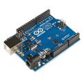
Arduino UNO board (ATmega328)
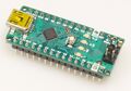
Arduino Nano board (ATmega328)

Protocol
- This uses the extended SUMP protocol as implemented by sigrok in ols driver.
Problems
Everything looks almost fine, device loads in pulseview, but there are still some cosmetic issues left to tackle:
- Buffer is currently sent or parsed backwards (time goes from right to left/zero)!!! (not sure if problem lays in arduino code or sigrok)
- RLE (=continuous capture) is not properly implemented in sigrok/ols driver, therefore capture length is limited by device memory
- Maximum supported samplerate is reported by device and received by sigrok, but not reflected in pulseview GUI
- Triggering is still a work in progress, but generally works for samples below 1MHz. over 1MHz works for a basic busy wait trigger that doesn't store until after the trigger fires.