ARMFLY AX-Pro
 | |
| Status | supported |
|---|---|
| Source code | fx2lafw |
| Channels | 8 + 1 |
| Samplerate | 8ch @ 24MHz, 8+1ch @ 12MHz |
| Samplerate (state) | — |
| Triggers | none (SW-only) |
| Min/max voltage |
Digital: 0V — +5V Analog: ±10V (±20V max) |
| Threshold voltage | Fixed: VIH=1.4V, VIL=0.8V |
| Memory | none |
| Compression | none |
| Price range | $35-45 |
| Website | armfly.com |
The ARMFLY AX-Pro is a USB-based, 8-channel logic analyzer with up to 24MHz sampling rate, with 1 additional analog channel (theoretically 2, but only one of them can be used at a time; 3MHz analog bandwidth). Has been proven to be possible to work at 24MS/s also for the Analog channel even if the ADC max sample rate is 20MS/s (see resources).
It is a clone of the CWAV USBee AX-Pro. There is an "RS232 RS485 RS422 CAN converter" add-on board which also has a BNC connector for analog support.
In sigrok, we use the open-source fx2lafw firmware for this logic analyzer.
Note: fx2lafw currently doesn't support switching between the two possible analog channels, ACH1 will be used unconditionally.
See ARMFLY AX-Pro/Info for some more details (such as lsusb -v output) on the device.
Hardware
- Main chip: Cypress CY7C68013A-56LTXC (FX2LP)
- I2C EEPROM: Atmel ATML920 24C02N SU27 D
- Low-dropout voltage regulator: Advanced Monolithic Systems AMS1117-3.3
- Crystal: 24MHz
- ADC: Texas Instrument TLC5510IPW, 8-Bit, 20 MS/s ADC Single Channel
- OpAmp: Texas Instrument LMV358 Dual Low-Voltage Rail-to-Rail Output Operational Amplifier
- OpAmp: Analog Devices AD8065 (SMD marking "HRA")
- Multiplexor: (I do not see it. Is it U5?)
- Edge-Triggered D-Type Flip-Flops"": HC574 (U15)
- ...
Photos
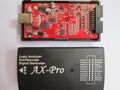
AX-Pro
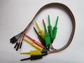
Cables
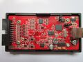
PCB, front


Protocol
Since we use the open-source fx2lafw firmware for this device, we don't need to know the protocol.
Hardware configuration (V.5)
- PA0 -> Select the Analog Source (Channel 1 or 2)
- PA1-7 are not connected
- CTL0 -> not connected
- CTL1 (connected with RDY1) -> CLK Pin (external)
- CTL2 -> provide the clock to the ADC
- PORTB -> Digital Data (8 pins, external)
- PORTD -> ADC Data