Difference between revisions of "Saleae Logic16"
Uwe Hermann (talk | contribs) (More ICs, datasheets.) |
(→Protocol: Decrypted the configuration transfers) |
||
| Line 61: | Line 61: | ||
'''Configuration''': | '''Configuration''': | ||
Endpoint 1 is used for configuration of the analyzer. Two kinds of transfers are used; a 3 byte out transfer starting with | Endpoint 1 is used for configuration of the analyzer. The transfers are "encrypted" using a simple series of additions and XORs. Two kinds of transfers are used; a 3 byte out transfer starting with 0x81 followed by a 1 byte in transfer, and a 4 byte out transfer starting with 0x80. It's quite plausible that these provide raw read/write access to memory locations. | ||
{| class="wikitable" | {| class="wikitable" | ||
| Line 67: | Line 67: | ||
|- | |- | ||
|3 channels | |3 channels | ||
|<span style="background-color: yellow"> | |<tt><span style="background-color: yellow">0x80 0x01 0x02 0x07</span> <span style="background-color: cyan">0x80 0x01 0x03 0x00</span></tt> | ||
|- | |- | ||
|6 channels | |6 channels | ||
|<span style="background-color: yellow"> | |<tt><span style="background-color: yellow">0x80 0x01 0x02 0x3f</span> <span style="background-color: cyan">0x80 0x01 0x03 0x00</span></tt> | ||
|- | |- | ||
|9 channels | |9 channels | ||
|<span style="background-color: yellow"> | |<tt><span style="background-color: yellow">0x80 0x01 0x02 0xff</span> <span style="background-color: cyan">0x80 0x01 0x03 0x01</span></tt> | ||
|} | |} | ||
| Line 80: | Line 80: | ||
|- | |- | ||
|500 kHz | |500 kHz | ||
|<span style="background-color: yellow"> | |<tt><span style="background-color: yellow">0x80 0x01 0x0a 0x00</span> <span style="background-color: cyan">0x80 0x01 0x04 0xc7</span></tt> | ||
|- | |- | ||
|8 MHz | |8 MHz | ||
|<span style="background-color: yellow"> | |<tt><span style="background-color: yellow">0x80 0x01 0x0a 0x01</span> <span style="background-color: cyan">0x80 0x01 0x04 0x13</span></tt> | ||
|} | |} | ||
Revision as of 18:07, 24 July 2013
 | |
| Status | planned |
|---|---|
| Channels | 2/4/8/16 |
| Samplerate | 100/50/25/12.5MHz |
| Samplerate (state) | — |
| Triggers | none (SW-only) |
| Min/max voltage | -0.9V — 6V |
| Threshold voltage |
configurable: for 1.8V to 3.6V systems: VIH=1.4V, VIL=0.7V for 5V systems: VIH=3.6V, VIL=1.4V |
| Memory | none |
| Compression | yes |
| Website | saleae.com |
The Saleae Logic16 is a USB-based, 16-channel logic analyzer with 100/50/25/12.5MHz sampling rate (at 2/4/8/16 enabled channels).
The case requires a Torx T5 screwdriver to open.
See Saleae Logic16/Info for more details (such as lsusb -vvv output) about the device.
See Saleae Logic for the predecessor product of the Saleae Logic16.
Hardware
- FPGA: Xilinx Spartan-3A XC3S200A, 200K gates (datasheeet)
- USB interface chip: Cypress CY7C68013A-56PVXC (FX2LP) (datasheet)
- Ultralow capacitance ESD protection: 4x ST DVIULC6-4SC6 (datasheet)
- I2C EEPROM: Unknown. Marking: "B2TH".
- ?: 2x Unknown 5-pin IC. Markings: "189Z" and "189C".
- ?: 2x Unknown 3-pin IC. Markings: "72Y7".
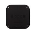
Photos

Device, front
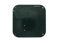
Device, bottom
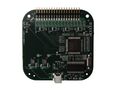
PCB, top
PCB, bottom


Firmware
The firmware for the FX2LP is embedded in the vendor application as a set of Intel HEX lines. Each line is uploaded individually with a separate control transfer. The firmware currently occupies the address range [0x0000-0x145d], but is uploaded out of order. TODO: Make a tool to extract the firmware from the application binary.
See Saleae Logic16/Firmware for more details on the vendor firmware.
Protocol
Sample format:
The samples (as received via USB) for the enabled probes (3, 6, 9, or 16) are organized as follows:
0xLL 0xLL 0xMM 0xMM 0xNN 0xNN 0xPP 0xPP 0xQQ 0xQQ 0xRR 0xRR ...
In the above example, 3 probes are enabled. For each probe there are 2 bytes / 16 bits (e.g. 0xLL 0xLL for probe 0), then the next probe's data is received (0xMM 0xMM for probe 1), then 0xNN 0xNN for probe 2. When 2 bytes have been received for all enabled probes, the process restarts with probe 0 again.
The 16 bits of data per probe seem to contain the pin state of the respective probe (1: high, 0: low) at 16 different sampling points/times (which ones depends on the samplerate).
Configuration:
Endpoint 1 is used for configuration of the analyzer. The transfers are "encrypted" using a simple series of additions and XORs. Two kinds of transfers are used; a 3 byte out transfer starting with 0x81 followed by a 1 byte in transfer, and a 4 byte out transfer starting with 0x80. It's quite plausible that these provide raw read/write access to memory locations.
| Channel number configuration | |
|---|---|
| 3 channels | 0x80 0x01 0x02 0x07 0x80 0x01 0x03 0x00 |
| 6 channels | 0x80 0x01 0x02 0x3f 0x80 0x01 0x03 0x00 |
| 9 channels | 0x80 0x01 0x02 0xff 0x80 0x01 0x03 0x01 |
| Sampling frequency | |
|---|---|
| 500 kHz | 0x80 0x01 0x0a 0x00 0x80 0x01 0x04 0xc7 |
| 8 MHz | 0x80 0x01 0x0a 0x01 0x80 0x01 0x04 0x13 |