Difference between revisions of "HT USBee-AxPro"
Uwe Hermann (talk | contribs) |
|||
| Line 44: | Line 44: | ||
! # !! Pin !! Destination !! Remark | ! # !! Pin !! Destination !! Remark | ||
|- | |- | ||
| || | | || CTL2 || ADC_CLK || ADC clock | ||
|- | |- | ||
| || PD0..7 || ADC_D1..8 || ADC data output | | || PD0..7 || ADC_D1..8 || ADC data output | ||
| Line 53: | Line 53: | ||
* ... | * ... | ||
=== Pin mappings === | |||
The FX2 CTL2 and PD0..7 pins are mapped exactly like the '''HT2013 V5.00''' version. The TLC5510I OE# pin is tied to GND. | |||
== Photos == | == Photos == | ||
| Line 58: | Line 62: | ||
'''HT2013 V5.00''': | '''HT2013 V5.00''': | ||
<gallery> | <gallery> | ||
File:Ht-usbee-axpro_package.jpg |<small>Device package</small> | |||
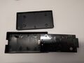
File:Ht-usbee case front.jpg |<small>Case, front</small> | |||
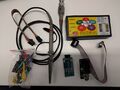
File:Ht-usbee device.jpg |<small>Device</small> | |||
File:Ht-usbee pcb front.jpg |<small>PCB, front</small> | File:Ht-usbee pcb front.jpg |<small>PCB, front</small> | ||
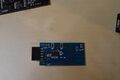
File:PCB3.jpg |<small>PCB, front</small> | |||
File:Ht-usbee pcb.jpg |<small>PCB, front</small> | File:Ht-usbee pcb.jpg |<small>PCB, front</small> | ||
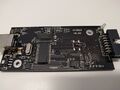
File:Ht-usbee backside.jpg |<small>PCB, back</small> | File:Ht-usbee backside.jpg |<small>PCB, back</small> | ||
File:TLC5510I.jpg |<small>TLC5510I</small> | File:TLC5510I.jpg |<small>TLC5510I</small> | ||
File:STM8_1.jpg |<small>STM8 1</small> | File:STM8_1.jpg |<small>STM8 1</small> | ||
File:SM8_2.jpg |<small>STM8 2</small> | File:SM8_2.jpg |<small>STM8 2</small> | ||
File:Probe_adaptor.jpg |<small> | File:Probe_adaptor.jpg |<small>Probe adaptor</small> | ||
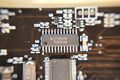
File:FX2.jpg |<small>FX2</small> | File:FX2.jpg |<small>FX2</small> | ||
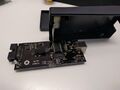
File:Expansion_board.jpg |<small> | File:Expansion_board.jpg |<small>Expansion board</small> | ||
File:AMS1117.jpg |<small>AMS1117</small> | File:AMS1117.jpg |<small>AMS1117</small> | ||
File:7660.jpg |<small>7660</small> | File:7660.jpg |<small>7660</small> | ||
Revision as of 16:14, 27 May 2016
 | |
| Status | supported |
|---|---|
| Source code | fx2lafw |
| Channels | 8 |
| Samplerate | 24MHz |
| Samplerate (state) | — |
| Triggers | none (SW-only) |
| Min/max voltage |
Digital: -1V — +6V Analog: ±10V (±20V max) |
| Threshold voltage | Fixed: VIH=1.6V, VIL=1.4V |
| Memory | none |
| Compression | none |
The HT USBee-AxPro is a USB-based, 8-channel logic analyzer with up to 24MHz sampling rate, with 1 additional analog channel.
It is able to switch between USBee AX-Pro, Salea Logic and Altera USB blaster mode via a button. When pressing the button the USB VID/PID changes.
It is a clone of the CWAV USBee AX-Pro.
In sigrok, we use the open-source fx2lafw firmware for this logic analyzer.
Hardware
HT2013 V5.00:
- Main chip: Cypress CY7C68013A-56SSOP (FX2LP)
- 64Kbit I²C EEPROM: Microchip 24LC641
- 2Kbit I²C EEPROM: Microchip 24LC02B
- Auxiliary 8051 chip: ST STM8S003F3 (used for handling the button)
- Supply voltage regulator: Advanced Monolithic Systems AMS1117-3.3
- Analog-to-digital converter: Texas Instruments TLC5510I
- Analog input amplifiers: Analog Devices AD8065 (SMD marking "HRA")
- Analog amplifiers negative supply: Intersil ICL7660 (7660 AIBAZ V120428A)
- Crystal: 24MHz
FX2LP pin mappings
| # | Pin | Destination | Remark |
|---|---|---|---|
| CTL2 | ADC_CLK | ADC clock | |
| PD0..7 | ADC_D1..8 | ADC data output |
HT_V6.0:
- ...
Pin mappings
The FX2 CTL2 and PD0..7 pins are mapped exactly like the HT2013 V5.00 version. The TLC5510I OE# pin is tied to GND.
Photos
HT2013 V5.00:
Device package
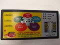
Case, front
Device
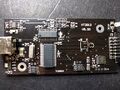
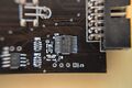
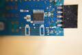
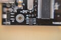
PCB, front
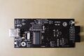
PCB, front
PCB, front
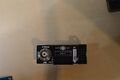
PCB, back
TLC5510I
STM8 1
STM8 2
Probe adaptor
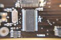
FX2
Expansion board
AMS1117
7660
24LC64
24LC02B


HT_V6.0:
Protocol
Since we use the open-source fx2lafw firmware for this device, we don't need to know the protocol.